News – Those Early Years of Pre-Production Automatic Height Control System Components
As seen in Modern Lady, March 2004
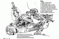
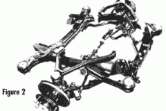
Let’s start with the evolution of the 1965 Rolls-Royce Silver Shadow and Bentley T series cars. After ten years of development behind the Motor Cars Series, the engineers decided that the best combination for ride and handling was to mount independent front & rear subframes (see Fig. 1 & 2).
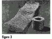
There were some drawbacks, using independent suspensions; this new type of body construction called (Monocoque Shell) transmitted a lot of road noise, There were some solutions to stop the transmission of road noise. The first was to mount front and rear sub-frames and the second was to use a special type of bushings. Instead of rubber mounts, the new type called Vibrashock used pads made from a very fine stainless steel wire knitted into an open meshed sleeve which is then crimped and rolled into a round symmetrical cushion and compacted by compression in a die to a point beyond the elastic limit of the wire (see Fig. 3)
Now this is where the fun starts. With one problem, solved a new one begins. With the new type of independent wishbone suspension the use of softer rear coil springs were used. While driving normally down the road at a steady rate of speed, the height of the rear suspension allows about three and a half inches of free wheel compress movement and a five and a half inch rebound directional movemenf. Compression and rebound movement could be used up by simply hitting large bumps, accelerating the vehicle heavily or just having the vehicle weight at its limit (five passengers, full tank of fuel, trunk full of stuff, maybe just your mother inlaw). Instead of using a constant veocity universal joint, the engineers decided to use a ball and trunnion joint, better known as “Detroit Pots System” which connects to the rear differential assembly (see Fig. 1).
The rear inner axle half shafts of this system will not rotate at a constant speed if the axle shafts are not at proper standing height. They will wobble and cause a fierce vibration depending on the. pitch up or down of the half shafts with a heavy torque load from the engine or just weight applied to the rear of the car (see Fig. 1). This is why the automatic height control system was adopted to the rear suspension first, to maintain the level at a predetermined height at al! kinds of conditions.
The automatic height correction for the rear system is provided by means of two leveling sensing valves and connecting links that are connected to both rear wishbone trailing arms. The sensing valves are mounted stationary at the ends of the rear sub-frame and sense movement by the connecting linkage to the trailing arms (see Fig. 1 & 4)
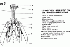
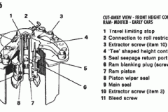
he hydraulic ram housings are mounted stationary to the body on top of the shock towers and the ram portion is screwed on the top ends of the rubber isolator cones, with the springs just below. The hydraulic Roms operate at hydraulic pressures of 1,150 to 2,500 Ibs. (see Fig. 1,5, and 6)
The leveling system works very slowly when the vehicle is being driven, but when the transmission gear shift selector is moved to park or neutral and if any of the four doors are opened, the system switches quickly to fast level the vehicle. This is achieved by a fast leveling electrical solenoid valve that is mounted stationary to the rear sub-frame. There are two valves, high and low pressure resfrictors used to control the flow rate of the brake fluid to the system components (see Fig. 1).
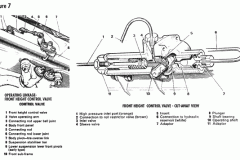
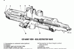
The front leveling system gave the front suspension a notably pitch free travel and eliminated the nose-dip under braking and most of the nose up surge under fierce acceleration that the prior Silver Cloud series had. The front eveling control sensing valve is mounted stationary to the middle of the front sub-frame and has a connecting link to the front anti sway bar that moves up and down with the sway bar (see Fig. 7). Both front hydraulic rams work simultaneously to ensure the rams keep in step: they are interconnected through the roll restrictor valve mounted on the top left fender (see Fig. 8).
Now, let us talk about those early years of trial and error. The first problem was the roll restrictor valve that was situated under the engine compartment, mounted on the left upper inner fender panel (see Fig. 8). The roll restrictor valve would just start leaking brake fluid while you were driving down the road and you know what happens when it makes contact with the paintwork: instant paint remover. Guaranteed to do the job right the first time or your money back!
I remember a story Cal West had told me about one of his experiences in the early days at BMC, a Rolls-Royce dealer in Son Francisco, CA. Cal was called to take a look at a customer car, which had come in for a brake fluid leak. The whole left side of the car looked like the paint was melting off the car: it was running everywhere. The roll restrictor valve had hemorrhaged and the air that was passing from under the car was blowing the brake fluid from under the hood and up and over the fender and across the side of the car while the customer was driving along.
The second problem was the panic stop syndrome. Let’s say if you were driving merrily along and some moron cut you off and you had to slam on the brakes, well, this might ruin your day for sure. The front leveling sensing valve connecting link rod would raise up and catch the tip of the engine fan blade and the one blades will twist and drill a hole in the radiator core leaving you on side of road saying to yourself — What just happened! (see Fig. 7)
The third problem was the cloth rapped brake hoses: they were bursting all around the car. Fixed metal pipes with new mounting hardware and flexible stainless steel lines were ultimately retrofitted. By the year 1970, the front leveling system had been deleted from the vehicles and a service kit was available to deactivate the front system for vehicles already in service. Service bulletin number SY/G37 was circulated to all distributors.
Submit your review | |

